


What's the bias tees?
A bias tee is a three-port network used for setting the DC bias point of some electronic components without disturbing other components. The bias tee is a diplexer. The low-frequency port is used to set the bias; the high-frequency port passes the radio-frequency signals but blocks the biasing levels; the combined port connects to the device, which sees both the bias and RF. It is called a tee because the 3 ports are often arranged in the shape of a T.
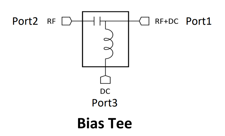
Conceptually, the bias tee or bias tees or bias-t or Bias-T can be viewed as an ideal capacitor that allows AC through but blocks the DC bias and an ideal inductor that blocks AC but allows DC. Although some bias tees can be made with a simple inductor and capacitor, wideband bias tees are considerably more complicated because practical components have parasitic elements.
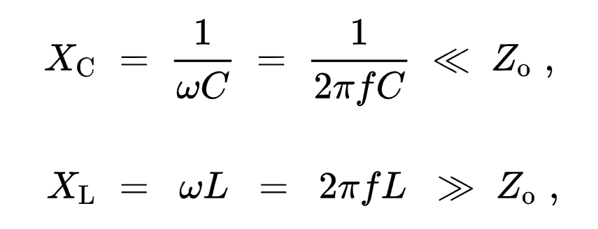
where ĶØ is the angular frequency (in radians per second) and f is the frequency (in Hertz).
Bias tees are designed to operate over a range of signal frequencies. The reactances are chosen to have minimal impact at the lowest frequency.
 At a high enough frequency, the stray capacitance presents a low-impedance shunt path for the RF signal, and the bias tee becomes ineffective. Practical wide-band bias tees must use elaborate circuit topologies to avoid the shunt path. Instead of one inductor, there will be a string of inductors in series, each with its own high resonant frequency, in addition to lower composite resonances shared between them. Additional resistors and capacitors will be inserted to prevent resonances. For example, a Picosecond Pulse Labs model 5580 bias tee works from 10 kHz to 15 GHz. Consequently, the simple design would need an inductance of at least 800 ĶĖH (XL about j 50 ohms at 10 kHz), and that inductor must still look like an inductor at 15 GHz. However, a typical commercial 820 ĶĖH inductor has a self-resonant frequency near 1.8 MHz ĻC four orders of magnitude too low.
Mike gives an example of a wideband microstrip bias tee covering 50 kHz to 1 GHz using four inductors (330 nH, 910 nH, 18 ĶĖH, and 470 ĶĖH) in series. His design cribbed from a commercial bias tee. He modeled parasitic element values, simulated results, and optimized component selection. To show the advantage of additional components, Mike provided a simulation of a bias tee that used just inductors and capacitors without Q suppression.Mike provides both simulated and actual performance details. Girardi duplicated and improved on Johnson's design and points out some additional construction issues.
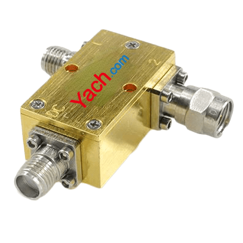
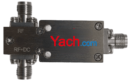
A bias tee or bias tees or bias-t or Bias-T is used to insert DC power into an AC signal to power remote antenna amplifiers or other devices. It is usually positioned at the receiving end of the coaxial cable to pass DC power from an external source to the coaxial cable running to powered device. A bias "T" consists of a feed inductor to deliver DC to a connector on the device side and a blocking capacitor to keep DC from passing through to the receiver. The RF signal is connected directly from one connector to the other with only the blocking capacitor in series. The internal blocking diode prevents damage to the bias "T" if reverse supply voltage is applied.
Bias tees or bias tees or bias-t or Bias-T are used in a variety of applications, but are generally used to provide an RF signal and (DC) power to a remote device where running two separate cables would not be advantageous. Biasing is often used with photodiodes (vacuum and solid state), Microchannel plate detectors, transistors, and triodes, so that high frequencies from the signal do not leak into a common power supply rail. Conversely, noise from the power supply does not appear on the signal line. Other examples include: Power over Ethernet, active antennas, low-noise amplifiers, and down converters.
The telephone line for plain old telephone service and some early microphones use a bias tee circuitĄŠoften with a gyrator replacing the inductorĄŠthis enables a thin cable with only 2 conductors to send power from the system to the device, and send audio from the device back to the system. Modern microphones often use 3 conductors in a phantom power circuit very similar to a bias tee circuit.
The construction of the horizontal bar of the T is based on the rigid coaxial cable with air as dielectric. The radius is chosen to be as large as possible without allowing higher modes. The design of a bias "T" is based upon power going out to the remote device, but not being seen by the base station or receiver. It does this by using a capacitor on the RF output terminal, effectively creating an open circuit for the DC current. The incoming RF signal, or the one from the antenna, is the output for the DC power. This front-end of a bias "T" typically consists of a bandpass filter, a low noise amplifier, and a mixer coupled to a local oscillator.
At one point a small slice is cut out of the center conductor, therefore a capacitor is formed and low frequencies are blocked. This kind of capacitor has the advantage that it is nearly invisible to higher frequencies. To pass frequencies down to 1 MHz the capacitance has to be increased. A dielectric like NPO multiplies the capacitance by a factor of 65. The thickness of the capacitor has to be minimal without leading to electric breakdown in the dielectric, this means to avoid any peaks in the electric field and this means smooth electrodes with rounded edges and a dielectric protruding between the electrodes (doorknob design).

A stack of capacitors can be used, but every capacitor needs access to the surface of the inner conductor, because if it's hidden behind another capacitor the high frequencies won't see it, because the electric field needs a lot of time to travel through a dielectric with a high dielectric constant.
Coil:
A small coil made of fine wire with an air core or MnFeZn-core connects the inner conductor of one of the sides of the capacitor with the a port in the outer conductor leading down the T. Frequencies above 1 GHz hit the coil from the side and apply an equal electric field to the whole coil. Therefore, no higher modes are excited within the coil. Because of the inductiveness of the coil almost no current leaks from the center conductor to the port. Frequencies between 1 MHz and 1 GHz do leak into this port, so there is a second coil with a cone shaped core outside of the outer conductor, but inside of a housing to avoid interference with other components. This cone acts like a tapered transmission line transformer. It starts with a high impedance, so a lot of power will be reflected, but the rest will travel down the coil and there is some leakage into the low frequency port.
Any oscillations in the capacitor or the coil or the composed LC circuit are damped by the dielectric and the core. Also the small coil should have about 10 ohm resistance to further damp oscillations and avoid ripple on the transmitted spectrum.
- ÉÏŌŧÆŠĢšWork principle of bias-t [2022-05-04]
- ÏÂŌŧÆŠĢšHow to choose a bias tee? [2022-05-03]