


Work principle of bias-t
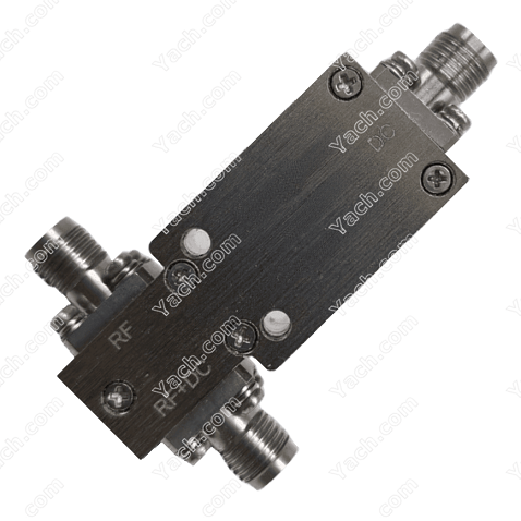
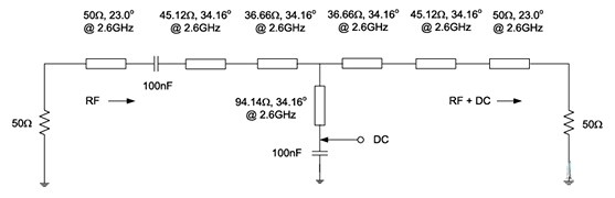
The bias tee is mainly used to inject DC current or voltage into the RF circuit, which does not affect the RF signal passing through the main transmission path. The common working block diagram is shown below:
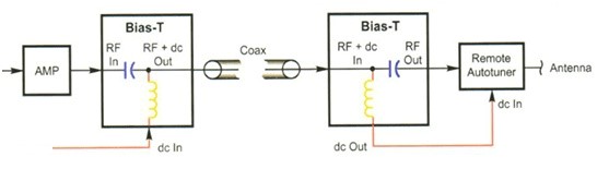
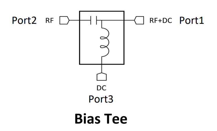
The DC port of the bias tees is composed of a feeding inductor, which is used to add DC bias-t to prevent the AC signal of the RF port from leaking to the power supply system. Under ideal conditions, the DC terminal will not have any impact on the RF terminal signal; The RF port is composed of a blocking capacitor, which is used to input RF signals and block the DC voltage of the bias tees port. Through this design, a RF cable is used to transmit DC and RF signals to the remote end at the same time.
The principle of the bias tees is simple, and there are few devices used, but similar to most passive devices, it is very difficult to design a good broadband bias device, which involves the accurate modeling and Simulation of basic components such as resistance capacitance sensing. For example, for a simple biaser model:
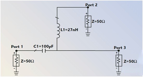
If only ideal capacitance and inductance models are used, the influence of transmission line is not considered:
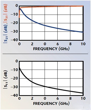
There will be a very good s parameter result:
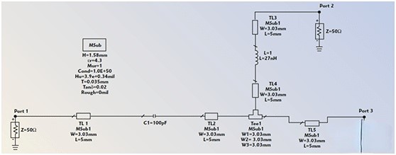
Because what we do is a microwave circuit, the modeling after introducing microstrip circuit is as follows:
Then the simulation results have a great impact, and a resonance peak is
generated near 8.2GHz: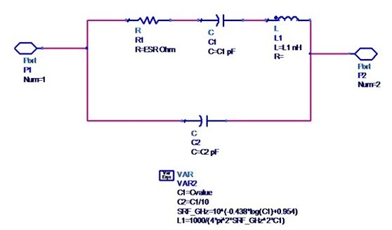
Replace the actual parameters and pads of capacitance and inductance, and the model is as follows:
The S-parameter results deteriorate further:
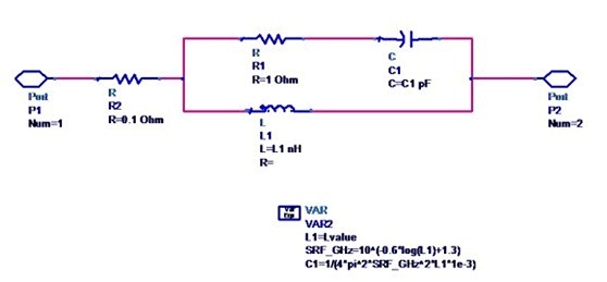
Therefore, two aspects should be paid attention to in broadband design. One is to analyze the parasitic parameters of discrete components. In addition, multi-level component cascade design should be used to expand the working frequency of the bias tees:

(inductance parasitic parameter model)
(capacitance parasitic parameter model)
Design examples of some broadband biasers:

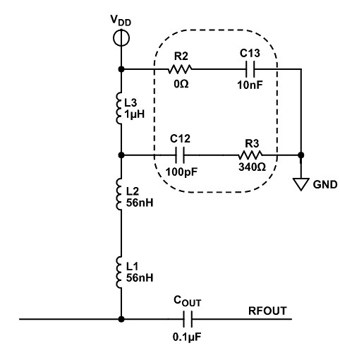
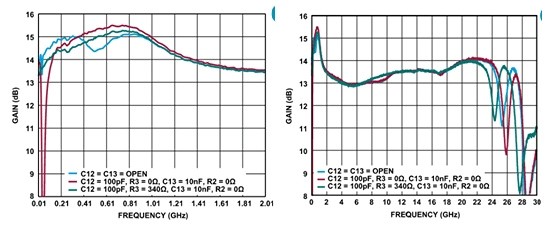
1) 10MHz-28GHz amplifier application circuit adopts the following discrete bias circuit:
Different capacitors, resistors and inductors produce different gain responses:
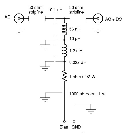
2) 5KHz ~ 3GHz bias tees
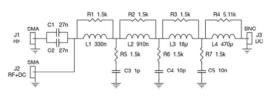
3) 300kHz ~ 2GHz bias tees
4) 71 ~ 76ghz bias tees
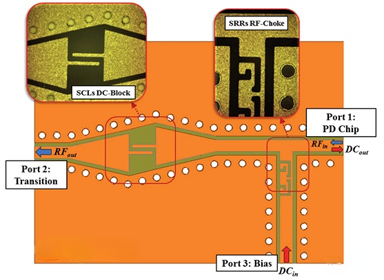
5) Broadband distributed parameter bias tees
- ÉÏŌŧÆŠĢšDesign Bias Tees [2022-05-04]
- ÏÂŌŧÆŠĢšWhat's the bias tees? [2022-05-03]