How to use a bias tee?
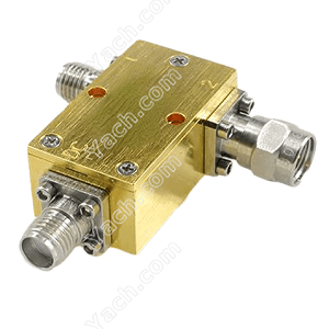
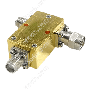
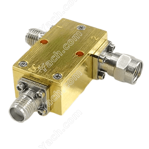 Bias Tees allow DC currents and/or voltages to flow to RF devices while blocking RF and microwave signals on the same line. A Bias Tee, for example, may be used to provide power to a transistor or amplifier circuit that requires a DC signal and will be interrupted by RF material on the signal and power lines. Pulsed bias tees, for example, allow for minimal distortion on current or voltage pulses for amplifiers and devices that need intermittent signals for biassing or control.
Biasing is commonly used for photodiodes (both vacuum and solid state), Microchannel plate detectors, transistors, and triodes to prevent high frequencies from leaking through a typical power supply rail. Noise from the power supply, on the other hand, does not appear on the signal line. Power over Ethernet active antennas, low-noise amplifiers, and down converters are some other examples.
A bias tee circuit—often with a gyrator replacing the inductor—allows a thin cable with just two conductors to transmit power from the system to the device and audio from the device back to the system for basic telephone service and some early microphones. In a phantom power circuit similar to a bias tee circuit, modern microphones often use three conductors.
The inner conductor of one of the sides of the capacitor is attached to a port in the outer conductor leading down the T by a small coil made of fine wire with an air core or MnFeZn-core. Frequencies greater than 1 GHz strike the coil from the side, generating an equivalent electric field in the coil.
As a result, no higher modes inside the coil are excited. Absolutely no current leaks from the centre conductor to the port due to the coil's inductive nature. Since frequencies between 1 MHz and 1 GHz leak into this port, a second coil with a cone-shaped core is mounted outside of the outer conductor but within a housing to prevent interference with other components.
This cone serves the same function as a tapered transmission line transformer. Since it begins with a high impedance, a lot of power is reflected, but the rest travels down the coil and leaks into the low frequency outlet.
- 上一篇:Bias Circuit Design for Microwave Amplifiers [2022-05-04]
- 下一篇:What is the bias tee circuit [2022-05-04]


