


Working principle and application of coupler
 In microwave system, one channel of microwave power needs to be divided into several channels in proportion, which is the problem of power distribution. The components that realize this function are called power distribution components, namely couplers, which mainly include directional couplers, power distributors and various microwave branch devices. Optocoupler is a photoelectric conversion device that uses light as the medium to transmit electrical signals. It consists of a light source and a light receiver. The light source and the light receiver are assembled in the same closed shell and isolated from each other with transparent insulators. The light source pin is the input end, the light receiver pin is the output end, the common light source is led, and the light receiver is photodiode, photosensitive triode, etc. There are many types of optocouplers, including photodiode type, photoelectric triode type, photosensitive resistance type, optically controlled thyristor type, photoelectric Darlington type, integrated circuit type, etc., as shown in Figure 1 below (the appearance includes metal shell package, plastic package, dual in-line plug, etc.).
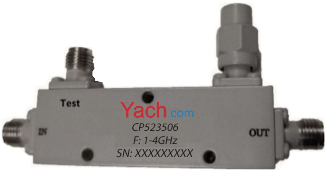
The insertion loss of coupler with coupling degree of − 10dB is − 0.5dB. Take the absolute value and consider the dielectric loss. Generally, the insertion loss is large. This is a different manufacturer. Generally, the insertion loss is about 0.7 dB.
If the input port power is 15dBm, the coupler coupling port power is 15dbm-10db = 5dBm and the output port power is 15dbm-0.7db = 14.3dbm.
Here, many people will ask such a question: 5dBm + 14.3dbm > 15dBm, energy is not conserved, why? The reason is simple. Cannot add quantity in DBM.
An electric signal is added to the input end of the optocoupler to make the light source emit light. The intensity of the light depends on the size of the excitation current. After the light shines on the packaged optical receiver, the photoelectric current is generated due to the photoelectric effect and led out by the output end of the optical receiver, so as to realize the electric optical electric conversion.
1. Working characteristics (taking photosensitive triode as an example)
The internal common mode rejection ratio of optocoupler is very high Since the coupling capacitance between the light emitting tube and the optical receiver is very small (within 2pF), the common mode input voltage has little effect on the output current through the inter pole coupling capacitance, so the common mode rejection ratio is very high.
2. Output characteristics
The output characteristic of the optocoupler refers to the relationship between the bias voltage VCE applied by the photosensitive tube and the output current IC under a certain luminous current if. When if = 0, the LED does not emit light. At this time, the collector output current of phototransistor is called dark current, which is usually very small. When if > 0, under the action of an if, the corresponding IC is basically independent of VCE. The change between IC and if is linear. The output characteristics of optocoupler measured by semiconductor tube characteristic grapher are similar to those of ordinary crystal triode.
3. Optocoupler can be used as linear coupler
A bias current is provided on the LED, and then the signal voltage is coupled to the LED through a resistor. In this way, the phototransistor receives the optical signal with the increase and decrease of bias current, and its output current will change linearly with the input signal voltage. The optocoupler can also work in the switching state to transmit pulse signals. When transmitting pulse signal, there is a certain delay time between input signal and output signal, and the input and output delay times of optocouplers with different structures are very different.
- ÉÏŌŧÆŠĢšHow to choose a bias tee? [2022-05-03]
- ÏÂŌŧÆŠĢšļôĀëÆũÓëŧ·ÐÎÆũÔÚ5GÖÐĩÄÓĶÓà [2021-12-03]