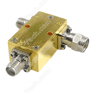
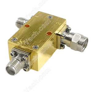
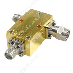
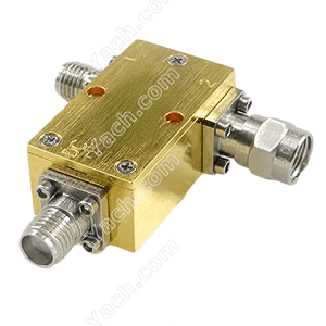
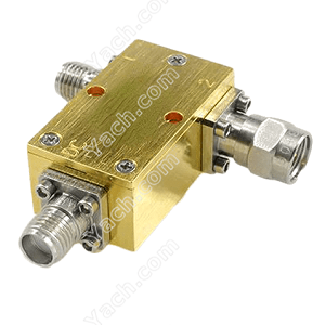
Maximum resolution of the bias tees
2022-05-14 13:14:12 点击:
 Bias tees: the phenomenon of DC signal component in AC signal is also DC offset. This feature is available on many PicoScope. When used correctly, it can return the vertical resolution, otherwise it will be lost when measuring small signals.
The analog bias adds a DC voltage to the input signal. If the signal is out of the range of the analog-to-digital converter (ADC) of the oscilloscope, the bias-t can be used to restore the signal to the range:
The waveform above shows the analog LVDS signal (half of the differential pair). We chose the ± 2V range, which is the most sensitive range that allows the signal to fit the screen. Although the oscilloscope has 8-bit resolution, which is equivalent to 256 different voltage levels, the signal only accounts for a small part of this range: 350mV out of a total of 4V, or only 22 voltage levels. This level number means that we only use the ADC 8-bit resolution of log8 / log2 ≈ 4.5 bits.
Amplify this signal to show the effect of this low resolution:
Using a scale, we measured a quantization noise of 16mv. As expected, this is close to an ADC level: 4V / 256 ≈ 15.6mv.
Use analog offset
In PicoScope software, the drop-down menu of each channel shows all settings at a glance. We have set the DC bias to - 1.2V to eliminate the input common mode voltage.
Now that the signal is within 175mv ground, we can set the range to a more sensitive range, ± 200mV, without saturating the input circuit.
The signal now occupies a 350 MV range of a total of 400 mV, which corresponds to 256 of the 256 levels. Therefore, we use the 8-bit resolution of ADC with about log224 / log2 ≈ 7.8 bits: more than 3 bits, more than before. This enables us to measure the waveform with an accuracy of about 10 times.
Amplifying this waveform shows a great improvement in resolution compared with the above.
The scale shows that most quantization noise now occupies the range of 1.58 MV. Similarly, as expected, this is about one ADC level: 400mV / 256 ≈ 1.56mv, but this time the error is reduced to about one tenth of the ± 2V range.
Using AC coupling
On an oscilloscope without analog bias function, or when the analog bias range is insufficient, sometimes AC coupling can be used to eliminate DC bias from the input. When the signal has a stable DC component, the technology works, such as the ripple on the DC power supply. However, it does not work well for LVDS because the signal is not DC balanced and therefore does not have a constant average voltage. The average value drifts up and down according to the data mode, making it impossible to make accurate measurement.
Here, first, is a successful example of using AC coupling: a 10 volt track with some sinusoidal ripples.
Only a small part of the input range of the ADC is displayed. We can eliminate DC bias by selecting AC coupling, which allows us to choose a more sensitive input range. Now we can use almost full range resolution.
If we try the same technique as our LVDS waveform now, if we have a stable data flow, the result is acceptable. However, if a data burst occurs after a long period of inactivity, the AC coupling capacitor will begin to charge, producing an unpredictable bias voltage that decays over time.
We can amplify this waveform to show a single pulse, but we will not be able to make any DC measurements because there is no fixed ground reference.
In the example of a typical low-level signal (LVDS line), the analog bias function of our bias tee allows us to increase the sensitivity of the instrument ten times. This results in a tenfold increase in vertical measurement resolution. AC coupling is useful for stabilizing waveforms, such as ripple on power rails, but for the use of serial data streams
- 上一篇:PIN Diode Switches SW516190 [2022-05-14]
- 下一篇:Power Amplifiers PA8375223 [2022-05-14]


