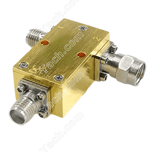
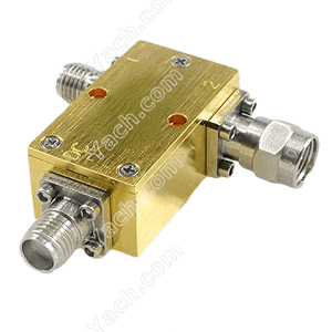
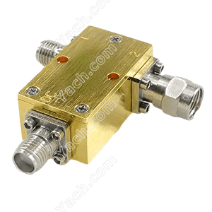
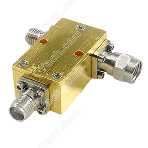
Bias Tees application in Microwave Amplifiers
Referring again to Fig. 1, the BJT circuit uses the conventional 4 resistor bias-t approach where the emitter resistor provides negative feedback stabilization against drift of the bias point with temperature or device parameter variation from batch to batch of devices. But, these circuits are not often used for RF applications because the biasing resistances also load the circuit and reduce the gain. Therefore, circuit techniques that permit use of a directly grounded source or emitter connection are preferred for high frequency amplifiers when implemented using discrete components on PC boards. In RFIC implementations, more flexibility is possible. One can use CC, CB, CG, CD connections as well as choosing device areas to optimize circuit performance.
Where possible, a better bias insertion method than a resistor or RFC is to insert a bias voltage using the matching network itself. It is possible that there is no series DC blocking or impedance matching capacitor when the shunt short-circuit stub or shunt inductor is connected to the input or output terminal of the equipment. The grounding terminal is bypassed by a grounding capacitor with low impedance over the entire frequency range.
- 上一篇:What is a power amplifier? [2022-05-06]
- 下一篇:Bias Circuit Design for Microwave Amplifiers [2022-05-04]


