


How to choose an RF Switch?
With the recent surge in the availability of RF switch products for test system development, it is becoming more and more difficult to choose the right products for your application. Most RF suppliers use two main specifications to describe their RF switch products - topology and bandwidth ( for example, RF Switches SW516169 and RF switch matrix series). Although these specifications are indeed important in the evaluation stage, they do not provide enough information for buyers to make informed purchase decisions. The following seven important specifications must be considered when RF Switching Networks:
*Characteristic impedance
*Bandwidth
*Topology
*Insertion loss
*Return loss and voltage standing wave ratio (VSWR)
*Isolation and crosstalk
*Rise time
Before discussing the characteristic impedance and other RF switch specifications, it is necessary to understand the difference between the mode of signal propagation in DC circuit and RF system. In the DC circuit or the circuit with low propagation signal frequency, the signal voltage at different points on the cable in the signal path changes very little. This is not the case in the case of RF or high-frequency signals, where the wavelength of the signal is very small compared to the length of the cable, allowing multiple cycles of the signal to propagate through the cable at the same time.
Consider an example in which two waves (signals) of different frequencies propagate through a 1 m coaxial cable. The frequency of the first signal is 1 MHz and the frequency of the second signal is 1 GHz.
In the case of signal 2, the length of the coaxial cable is much larger (almost five times) than the wavelength of the signal transmitted through it. Therefore, at any given time, multiple cycles of the signal will pass through the cable at the same time. Because of their small wavelength, high-frequency signals propagate through cables in the form of waves. Therefore, such signals will suffer reflection and power loss when propagating between different media (fluctuation theory). In the case of a circuit, this change in the medium occurs when the signal (wave) passes through system components with different characteristic impedances. Therefore, in order to minimize reflection and power loss, an RF system must be constructed using appropriate components with matching impedance.
Z 0 = characteristic impedance
L = inductance per unit length of RF transmission line, caused by the magnetic field formed around the conductor when the current flows through the conductor.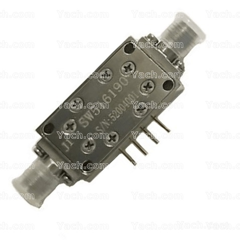
C = capacitance per unit length of RF transmission line. This is also the capacitance between the two conductors
R = DC resistance per unit length of RF transmission line
G = dielectric conductivity per length
ω = Frequency (radians / sec)
Since all components in the RF system must be impedance matched to minimize signal loss and reflection, component manufacturers have specially designed their equipment to have a characteristic impedance of 50 or 75 Ω. 50 Ω RF system constitutes the majority of RF market, including most communication systems. The number of 75 Ω RF systems is small, which is mainly used for video RF system. It is essential that engineers ensure that components such as cables and connectors and other instruments that may reside in the test system are impedance matched.
If the transmission line length of the signal transmission is greater than 0.01 of its own wavelength, there will be significant power loss in the signal. The "insertion loss" specification of the switching module is a measure of this power loss and signal attenuation. The insertion loss of the switching module at a specific frequency can be used to calculate the power loss or voltage attenuation caused by the opening signal at that frequency.
VSWR is the ratio of reflected wave to transmitted wave. As mentioned earlier, at higher frequencies, the signal adopts the form and shape of wave when passing through the transmission line or cable. For this reason, as in the case of sound and light waves, reflection occurs when the signal passes through different media, such as components with mismatched impedance. In the switch module, this mismatch may exist between the characteristic impedance of the connector, PCB wiring and the actual relay itself. Because VSWR is a measure of reflected wave power, it can also be used to measure power loss in transmission lines. When added to the input signal, the reflected wave will increase or decrease its net amplitude, depending on whether the reflected wave is in phase or out of phase with the input signal. The ratio of the maximum (when the reflected wave is in phase) to the minimum (when the reflected wave is out of phase) voltage in the "standing wave" mode is called VSWR. To learn how to calculate VSWR and return loss in RF system.
Topology is one of the most important characteristics to consider when selecting RF switch. Choosing a switch with the wrong topology will have a considerable impact on insertion loss and VSWR. The two main topology types available for RF are multiplexers and single pole double throw (SPDT) relays. A multiplexer is a switching system that routes multiple inputs to one output in turn and vice versa. The SPDT relay is a reduced version of the multiplexer. A Single SPDT relay can route two inputs to one output and vice versa. RF multiplexers usually consist of multiple SPDT relays.
Different applications require different RF switch topology combinations. For example, to perform an excitation response test on a 4-channel DUT, you can use a module with two independent 4x1 multiplexing groups. On the other hand, for tests analyzed from the outputs of eight independent DUTs, a module with a single 8X1 group is preferred. Since there are many RF switches available on the market, it is important to understand the best use of these different topologies in order to choose the best choice for your application.
By discussing two different ways to build a 7x1 multiplexer, the examples in FIGS. 9 and 10 will illustrate why it is preferable. The first method cascades two 4x1 multiplexers to build a single 7x1 multiplexer. The disadvantage of this setting is that it requires the signal from the DUT to pass through two switching modules (a total of four SPDT relays) before reaching the vector network analyzer (VNA). Therefore, the net insertion loss in the signal path is now the sum of the individual insertion loss specifications for each individual relay and cable in the system.
- 上一篇:Power Amplifiers PA8375157 [2022-05-16]
- 下一篇:PIN Diode Switches SW515246 [2022-05-15]